
Boas pessoal.
Eu estou a precisar de um chip ou um circuito capaz de colocar numa saída um pulso em resposta a detecção de um nível alto.
Se conhecerem algum integrado que consiga fazer isto, melhor, se não, algum esquema também serve.
Em anexo envio um esboço do que pretendo para se perceber melhor.
Thanks,
Pedro
Resposta em Puslo (É POSSIVEL?)

Re: Resposta em Puslo (É POSSIVEL?)
Já tenho feito no 555, mas o 555 só responde a um pulso.
Se na entrada se mantiver o nível lógico alto, a saída também se mantém a nível alto até que na entrada vá a nível baixo.
Pedro
Se na entrada se mantiver o nível lógico alto, a saída também se mantém a nível alto até que na entrada vá a nível baixo.
Pedro
-
PauloMalas

- Quadro de Honra

- Mensagens: 177
- Registado: 30 abr 2007, 00:29
- Localização: Souselo
- Contacto:
Re: Resposta em Puslo (É POSSIVEL?)
Monostable Multivibrator CD4538
CD4538 is a dual Monostable Multivibrator. When you trigger the chip the output sends off one single pulse or one high-low event.
The T+ pin 4 of U1a is the positive edge trigger or raising edge trigger input, the T- pin 5 is falling edge or negative edge trigger input. Now see the image of the single pulse above which shows both the edges, If this is the input pulse at pin 5 then the falling edge turns the output pin 6 from low to high, this output remains high for time T = R2 * C1 and then goes low again, The output Q at pin 6 also looks like the image of pulse above.
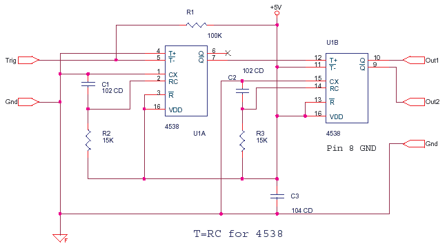
The Output pin 7 is the complementary state of pin 6, it is the reverse state or inverted form of pin 6 output.
Now why is a slope shown in the edges, this i have exaggerated a bit so that it can be explained. But then there is a slight slope due to gate input and output capacitance.
In fact if you had a wire or twisted track coming to the input and the R2C1 was in nano seconds, then you would see a ringing at the edges, a tiny peak or spike, which will have giga hertz frequency components, in fact a square way may be many sine waves put together, this you know from a spectrum analyzer.
CD4538B can give an output with pulse width of 1uS and above. 74HC4538 gives 120nS to 60 Seconds pulses. The above circuit produces a pulse of width T = R3 * C2 after a delay of T = R2 * C1. Some Chips formula is T = 0.7 * R * C .
CD4538 is a dual Monostable Multivibrator. When you trigger the chip the output sends off one single pulse or one high-low event.
The T+ pin 4 of U1a is the positive edge trigger or raising edge trigger input, the T- pin 5 is falling edge or negative edge trigger input. Now see the image of the single pulse above which shows both the edges, If this is the input pulse at pin 5 then the falling edge turns the output pin 6 from low to high, this output remains high for time T = R2 * C1 and then goes low again, The output Q at pin 6 also looks like the image of pulse above.
The Output pin 7 is the complementary state of pin 6, it is the reverse state or inverted form of pin 6 output.
Now why is a slope shown in the edges, this i have exaggerated a bit so that it can be explained. But then there is a slight slope due to gate input and output capacitance.
In fact if you had a wire or twisted track coming to the input and the R2C1 was in nano seconds, then you would see a ringing at the edges, a tiny peak or spike, which will have giga hertz frequency components, in fact a square way may be many sine waves put together, this you know from a spectrum analyzer.
CD4538B can give an output with pulse width of 1uS and above. 74HC4538 gives 120nS to 60 Seconds pulses. The above circuit produces a pulse of width T = R3 * C2 after a delay of T = R2 * C1. Some Chips formula is T = 0.7 * R * C .
pic's on the rocks
Tecnico de Electronica a trabalhar como picheleiro e electricista.
Tecnico de Electronica a trabalhar como picheleiro e electricista.
-
bmm.deoliveira
- Faça a sua apresentação

- Mensagens: 2
- Registado: 03 fev 2011, 14:41
Re: Resposta em Puslo (É POSSIVEL?)
Sempre tens uma solução possível neste link: http://www.circuitdb.com/circuits/id/196
Re: Resposta em Puslo (É POSSIVEL?)
Malta,
Para quem precisar de algo deste género, já tenho uma solução que funciona na perfeição.
Apresento esquema em seguida.
Cumps,
Pedro
Para quem precisar de algo deste género, já tenho uma solução que funciona na perfeição.
Apresento esquema em seguida.
Cumps,
Pedro
- Anexos
-
- im_2.png (8.79 KiB) Visto 1453 vezes
-
carlos_cfr7

- Quadro de Honra
- Mensagens: 619
- Registado: 11 jun 2007, 15:37
- Localização: Faro
- Agradecimento recebido: 1 vez
Re: Resposta em Puslo (É POSSIVEL?)
é a soluçao indicada - Flip-Flops RS 
Eng. de electrónica e telecomunicações